
Products


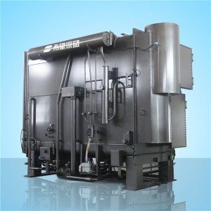
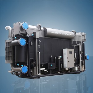
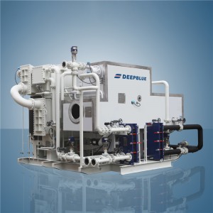
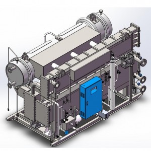
Steam&hot water absorption chiller
2.1 Working principle
In our daily life, as we all know that, we will feel cool if dripping some alcohol on the skin, that’s because the evaporation will absorb heat from our skin. Not only alcohol, all other kinds liquid will absorb surrounding heat while evaporation. And the lower the atmospheric pressure, the lower the evaporation temperature. For example, the water boiling temp is 100℃ under 1 atmosphere of pressure, but If the atmospheric pressure drops to 0.00891, the water boiling temp becomes to 5℃.That’s why under vacuum conditions, water can vaporize at very low temp.
That is the basic working principle of a LiBr absorption chiller. Water(refrigerant) vaporizes in the high-vacuum absorber and absorbs heat from the water which is to be cooled. The refrigerant vapor is then absorbed by the LiBr solution(absorbent) and circulated by pumps. The process repeats.
2.2 Flow diagram
The dilute solution exiting the absorber is pumped by generator pump , heated via the low-temperature heat exchanger and condensate heat exchanger, then enters the LTG. Within the LTG, the dilute solution is heated to boiling by high-pressure, high-temperature refrigerant vapor flowing through the tubes from the HTG and by the driving hot water, producing refrigerant vapor and concentrating the solution into intermediate solution.
A portion of the intermediate solution is pumped by solution pump through a high-temperature heat exchanger into the HTG. Within the HTG, the intermediate solution is heated by driven steam, producing high-pressure, high-temperature refrigerant vapor. The solution further concentrates into a concentrated solution.
The high-pressure, high-temperature refrigerant vapor generated in the HTG heats the dilute solution in the LTG before condensing into refrigerant water. After throttling to reduce pressure, it enters the condenser alongside the refrigerant vapor produced in the LTG. There, it is cooled by the cooling water, becoming refrigerant water corresponding to the condensing pressure.
The refrigerant water produced in the condenser enters the evaporator after throttling through a U-type tube. Due to the low pressure in the evaporator, part of the refrigerant water evaporates. The majority of the refrigerant water is pumped by the refrigerant pump and sprayed onto the evaporator tube. It absorbs heat from the chilled water, lowering the temperature of the chilled water within the tub and achieving the refrigeration effect.
The concentrated solution exiting the HTG flows through a high-temperature heat exchanger, where it mixes with another portion of intermediate solution from the LTG. This mixture is then pumped by the absorber pump into the absorber, where it sprays over the absorber tube. Cooled by the circulating cooling water within the tubes, its temperature decreases. It then absorbs refrigerant vapor from the evaporator, transforming into a dilute solution. Thus, the mixed solution continuously absorbs refrigerant vapor generated by the evaporation of refrigerant water in the evaporator, sustaining the evaporation process. The lithium bromide solution, diluted by absorbing refrigerant vapor from the evaporator, is then pumped by LTG pump to the LTG, completing one refrigeration cycle. This cycle repeats endlessly, enabling the evaporator to continuously supply low-temperature chilled water for air conditioning or industrial cooling applications.

Fig. 2-1 Process Flow Diagram
2.3 Main Components and Functions
1. Generator
HTG Function: Using driven steam, moisture from the intermediate solution at LTG is evaporated into primary refrigerant vapor, concentrating the solution into a concentrated solution. The primary refrigerant vapor enters the LTG, while the concentrated solution flows to the HTHE.
LTG Function: The primary refrigerant vapor generated by driven hot water and HTG concentrates the dilute solution from the absorber into an intermediate solution. The primary refrigerant vapor is then converted into refrigerant water, which further produces secondary refrigerant vapor.
2. Condenser
Condenser Function: Condenses the secondary refrigerant vapour from LTG into water and cools down the primary refrigerant water from HTG, with heat being taken away by the cooling water.
3. Evaporator
Evaporator Function: By evaporating the refrigerant water, absorbs heat from the water flowing through the air conditioning system.
4. Absorber
Absorber Function: The concentrated solution absorbs the refrigerant vapour from the evaporator, with the heat being taken away by the cooling water.
5. Heat Exchanger
High temp. Heat Exchanger Function: Recovers heat from intermediated solution from HTG.
Low temp. Heat Exchanger Function: Recovers heat from concentrated solution from LTG.
Condensate W. Heat Exchanger Function: Recovers heat from the condensate of driven steam from the HTG to enhance the thermal efficiency of the unit, thereby reducing its steam consumption.
6. Automatic Air Purge System
System Function: The air purge system is ready to pump out the non-condensable air in the heat pump and maintain a high vacuum condition. During operation, the diluted solution flows at a high rate to produce a local low pressure zone around the ejector nozzle. Thus the non-condensable air is pumped out of the heat pump. The system operates simultaneously with the heat pump. While the heat pump is working, the automatic system helps maintain a high vacuum inside and ensure system performance and a maximized service life.
The air purge system is a system composed of the ejector, cooler, oil trap, air cylinder and valve.
7. Solution Pump
The solution pump is used to deliver the LiBr solution and secure the normal flow of liquid working mediums inside the heat pump.
The solution pump is a wholly-enclosed, canned centrifugal pump featuring zero liquid leakage, low noise, high explosion-proof performance, minimal maintenance and a long service life.
8. Refrigerant Pump
The refrigerant pump is used to deliver refrigerant water and ensure the normal spray of refrigerant water on the evaporator.
The refrigerant pump is a wholly-enclosed, canned centrifugal pump featuring zero liquid leakage, low noise, high explosion-proof performance, minimal maintenance and a long service life.
9. Vacuum Pump
The vacuum pump is used for vacuum purging at the start-up stage and air purging at the operation stage.
The vacuum pump features a rotary vane wheel. The button to its performance is vacuum oil management. The prevention of oil emulsification has an obviously positive impact on air purging performance and helps lengthen the service life.
10. Electric Cabinet
As the control center of the LiBr heat pump, the electrical cabinet houses the main controls and electrical components.
Waste Heat Recovery. Energy Conservation&Emission Reduction
It can be applied to recover LT waste hot water or LP steam in thermal power generation, oil drilling, petrochemical field, steel engineering, chemical processing field, etc. It can utilize river water, groundwater or other natural water source, converting LT hot water into HT hot water for the purpose of district heating or process heating.
Intelligent Control&Easy Operation
Fully automatic control, it can realize one-button On/Off, load regulation, solution concentration limit control and remote monitoring.
Artificial Intelligent Control System AI (V5.0)
■Fully-automatic control functions
The control system (AI, V5.0) is featured by powerful and complete functions, such as one-key start up/shutdown, timing on/off, mature safety protection system, multiple automatic adjustment, system interlock, expert system, human machine dialogue(multi languages), building automation interfaces, etc.
■Complete unit abnormality self-diagnosis and protection function
The control system (AI, V5.0) features 34 abnormality self-diagnosis&protection functions. Automatic steps will be taken by system according to level of an abnormality. This is intended to prevent accidents, minimize human labor and ensures a sustained, safe and stable operation of chiller.
■Unique load adjustment function
The control system (AI, V5.0) has a unique load adjustment function, which enables automatic adjustment of chiller output according to actual load. This function not only helps to reduce startup/shutdown time and dilution time, but also contributes to less idle work and energy consumption.
■Unique solution circulation volume control technology
The control system (AI, V5.0) employs an innovative ternary control technology to adjust solution circulation volume. Traditionally, only parameters of generator liquid level are used to control of solution circulation volume. This new technology combines merits of concentration&temperature of concentrated solution and liquid level in generator. Meanwhile, an advanced frequency-variable control technology is applied to solution pump to enable unit to achieve an optimal circulated solution volume. This technology improves operating efficiency and reduces startup time and energy consumption.
■Solution concentration control technology
The control system (AI, V5.0) uses a unique concentration control technology to enable real-time monitoring/control of concentration and volume of concentrated solution as well as hot water volume. This system can maintain chiller under safe and stable at high-concentration condition, improve chiller operating efficiency and prevent crystallization.
■Intelligent automatic air purge function
The control system (AI, V5.0) can realize real-time monitoring of vacuum condition and purge out the non-condensable air automatically.
■Unique dilution stop control
This control system (AI, V5.0) can control operation time of different pumps required for dilution operation according to concentrated solution concentration, ambient temperature and remaining refrigerant water volume. Therefore, an optimal concentration can be maintained for the chiller after shutdown. Crystallization is precluded and chiller re-start time is shortened.
■Working parameter management system
Through interface of this control system (AI, V5.0), operator can perform any of following operations for 12 critical parameters relating to chiller performance: real-time display, correction, setting. Records can be kept for historical operation events.
■Unit fault management system
If any prompt of occasional fault is displayed on operation interface, this control system(AI, V5.0) can locate and detail fault, propose a solution or trouble shooting guidance. Classification and statistical analyses of historical faults can be conducted to facilitate maintenance service provided by operators.